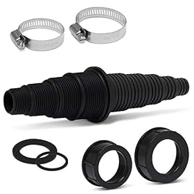
Friction loss in pond tubing reduces the water a pump can deliver. Learn how to estimate it from tubing size, flow rate, length, fittings, and elevation before choosing a pond pump.
Calculating friction loss in pond tubing
Friction loss is the pressure, or pump head, lost as water moves through pond tubing. It reduces the flow that reaches a waterfall, filter, stream, or fountain. To estimate it, you need the target flow rate, the tubing’s actual inside diameter, the total tubing length, and the losses caused by elbows, valves, fittings, and restrictions.
The most reliable approach is to use a friction-loss chart supplied by the tubing or pump manufacturer. Flexible, corrugated, kink-resistant, and smooth-wall tubing can have very different losses even when their stated diameter is similar.
The basic pond-pump calculation
Pump sizing usually involves total dynamic head, sometimes called total head:
Total dynamic head = static lift + tubing friction loss + fitting losses + equipment losses
The pump must be able to deliver your desired flow at that total head—not merely at its zero-head or maximum-flow rating.
Static lift
Static lift is the vertical distance from the pond’s water surface to the discharge point. Measure vertically, not along the tubing route. If the outlet is above the pond, the pump must overcome that elevation before friction is considered.
Tubing friction loss
Tubing friction increases with:
Higher flow rate
Smaller inside diameter
Longer tubing runs
Rough or corrugated inner walls
Kinks, crushing, and sharp bends
Dirty tubing or biological buildup
A small increase in tubing diameter can substantially reduce friction loss, especially on longer runs or higher-flow systems.
Fitting and equipment losses
Water also loses head as it passes through elbows, tees, valves, check valves, filter inlets, UV clarifiers, skimmers, and narrow fittings. Use manufacturer data when available. If data is unavailable, treating every fitting as negligible can result in an undersized pump.
Product prices and availability are accurate as of the date/time indicated and are subject to change. Any price and availability information displayed on Amazon.com at the time of purchase will apply to the purchase of this product.
A practical method for estimating friction loss
1. Set the required flow rate
Start with the amount of water the feature or filter needs. For a waterfall, stream, or fountain, use the design flow recommended for that feature. For a biological filter, follow the filter manufacturer’s flow guidance.
Do not use the pump’s advertised maximum flow as the design flow. Maximum flow is generally measured with little or no lift and no meaningful tubing resistance.
2. Measure the tubing run
Measure the actual one-way distance from the pump outlet to the discharge point. Include vertical and horizontal sections. Add enough length for routing around rocks, walls, and equipment rather than relying on a straight-line measurement.
If the tubing route may change, allow some extra length. A tight, kinked route can create more resistance than a slightly longer, smoothly routed one.
3. Confirm the actual inside diameter
Friction charts require inside diameter, not just the nominal tubing size. Two products labeled with the same general size may have different internal openings because of wall thickness or construction.
Check the tubing packaging or manufacturer’s data sheet. If you are measuring tubing directly, measure the clear opening inside the tube—not the outside diameter.
4. Find the friction loss on a chart
Use a chart that matches:
The tubing’s actual inside diameter
The tubing material and inner-wall construction
Your target flow rate
The unit you are using, such as feet of head per 100 feet of tubing
If the chart lists loss per 100 feet, use this calculation:
Tubing friction loss = chart loss × actual tubing length ÷ 100
For example, if a chart gives a loss of 8 feet of head per 100 feet and your run is 25 feet, the tubing portion would be 2 feet of head. This is an illustrative calculation; use the actual value from your tubing’s chart.
If your target flow falls between two chart values, use the higher flow value for a conservative estimate or interpolate only if the chart provides enough detail.
5. Add fitting losses
Count significant restrictions in the route, including:
Filter, UV clarifier, and waterfall inlet connections
Some charts express fittings as an equivalent length of straight tubing. In that case, add the equivalent lengths to the physical tubing length before calculating friction loss.
Other manufacturers list each component’s head loss directly. Add those losses to the tubing friction loss.
6. Add elevation and equipment head
Add the calculated friction loss to the static lift. Then include the head loss listed for filters, UV clarifiers, check valves, or other equipment at your intended flow rate.
The result is the approximate total head the pump must overcome while delivering the required flow.
Product prices and availability are accurate as of the date/time indicated and are subject to change. Any price and availability information displayed on Amazon.com at the time of purchase will apply to the purchase of this product.
Why tubing diameter matters so much
Narrow tubing creates higher water velocity and greater resistance. It can also force the pump to operate farther down its performance curve, where flow is lower.
Using a larger main line is often more effective than buying a larger pump and forcing water through a restrictive line. A larger pump connected to undersized tubing may consume more electricity, create more noise, and still fail to deliver the expected flow.
The tubing connection can also become the limiting point. A large line does not eliminate the restriction from a small pump outlet, reducer, valve, or filter port, but it can reduce losses through the rest of the run.
Product prices and availability are accurate as of the date/time indicated and are subject to change. Any price and availability information displayed on Amazon.com at the time of purchase will apply to the purchase of this product.
Smooth-wall versus corrugated tubing
Smooth-wall tubing generally has less internal resistance than tubing with a corrugated or ribbed interior of the same inside diameter. Corrugated tubing may be useful for flexibility and routing, but its friction-loss data should be treated separately from smooth-wall hose charts.
Do not apply a smooth-wall chart to corrugated tubing unless the manufacturer specifically says it is appropriate. The resulting pump calculation may be too optimistic.
Include a reasonable safety margin
Friction calculations are estimates. Real installations can differ because of:
Partially closed valves
Kinks or collapsed sections
Debris in the tubing
Biofilm and mineral buildup
Changes in water level
Actual pump performance differing from the published curve
Fittings that are smaller internally than expected
A modest design margin helps account for these variables. Avoid choosing a pump solely by adding an arbitrary large percentage, however. Compare the pump’s performance curve with the calculated total head and choose a model that can deliver the required flow at that point.
Common calculation mistakes
Using the pump’s maximum-flow number
Maximum flow does not represent output at your waterfall height, tubing length, or equipment resistance. Use the pump curve instead.
Measuring tubing by outside diameter
The inside opening controls water resistance. Use the manufacturer’s actual inside-diameter specification whenever possible.
Ignoring fittings
A short tubing run can still have significant resistance if it includes several restrictive fittings, a check valve, a UV unit, and a filter inlet.
Treating all tubing as equivalent
Material, interior texture, flexibility, and actual internal diameter affect friction. Use data for the specific tubing type.
Forgetting the return route
For a simple open waterfall, calculate the pumped supply route. In a closed plumbing loop or pressurized system, account for every relevant section of the circuit.
Confusing pressure loss with elevation
Friction loss and static lift are different parts of total head. A system can have low elevation but high friction, or high elevation with a relatively short, large-diameter line.
A simple worksheet
Record these values before selecting a pump:
Required flow: ___ gallons per hour
Static lift: ___ feet
Tubing inside diameter: ___ inches
Tubing type: smooth-wall, corrugated, or other
Tubing length: ___ feet
Tubing friction loss from the matching chart: ___ feet of head
Fitting and valve loss: ___ feet of head
Filter, UV, check-valve, or feature loss: ___ feet of head
Estimated total dynamic head: ___ feet
Then check the pump curve to see whether the pump delivers the required flow at the estimated total head.
When to recheck the calculation after installation
Recheck the system if the flow is noticeably lower than expected. First inspect the tubing for kinks, crushed sections, closed valves, blocked screens, and debris. Confirm that the tubing is connected to the intended pump outlet and that reducers or adapters have not created an unexpected restriction.
If the plumbing is clear but flow remains low, compare the pump’s rated curve with the actual total head. A different pump, larger tubing, fewer restrictions, or a shorter route may be more appropriate. Follow the pump and tubing manufacturers’ instructions, and disconnect electrical equipment before inspecting submerged equipment.
FAQ
What is friction loss in pond tubing?
Friction loss is the reduction in available pump pressure or head caused by water moving through tubing. It increases with flow rate, tubing length, small inside diameter, rough interiors, kinks, and restrictions.
How do I calculate pond tubing friction loss?
Find the loss for your actual tubing type, inside diameter, and flow rate on a manufacturer’s chart. Multiply the chart value by the tubing length divided by 100 if the chart is expressed per 100 feet, then add fitting and equipment losses.
Does larger pond tubing improve pump flow?
Usually, yes. Larger inside diameter reduces resistance, particularly on long runs and at higher flow rates. The pump outlet, fittings, valves, and filter ports can still limit the system.
Should I use a smooth-wall tubing chart for corrugated pond tubing?
No, not unless the tubing manufacturer confirms that the chart applies. Corrugated interiors can create different resistance from smooth-wall tubing of the same nominal size.
Why is my pond pump flow lower than the calculation?
Check for a clogged intake or filter, kinked tubing, closed valves, blocked fittings, air leaks on the suction side, incorrect tubing size, excessive elevation, and equipment losses that were left out of the estimate. Also compare the pump’s actual performance curve with the total head.